
Heat Pump & Hydronic System Skid — 3D Design & Visualization
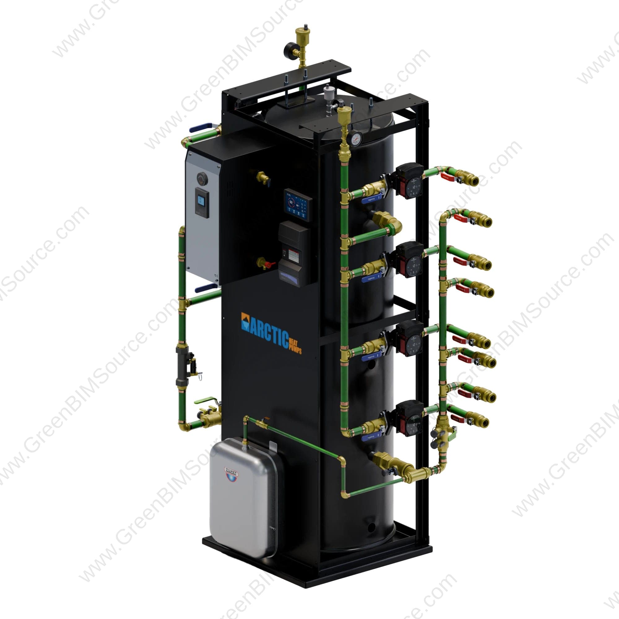
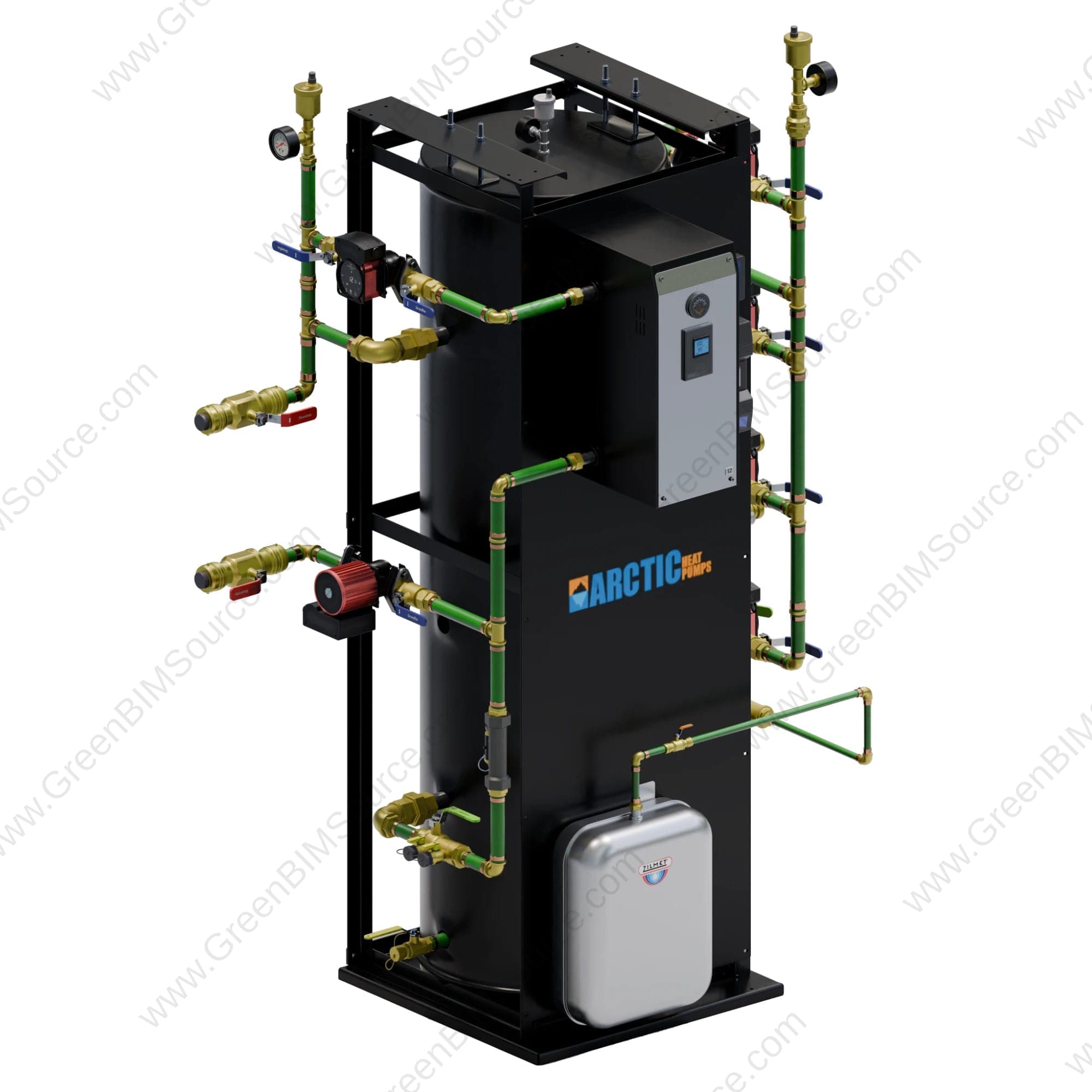
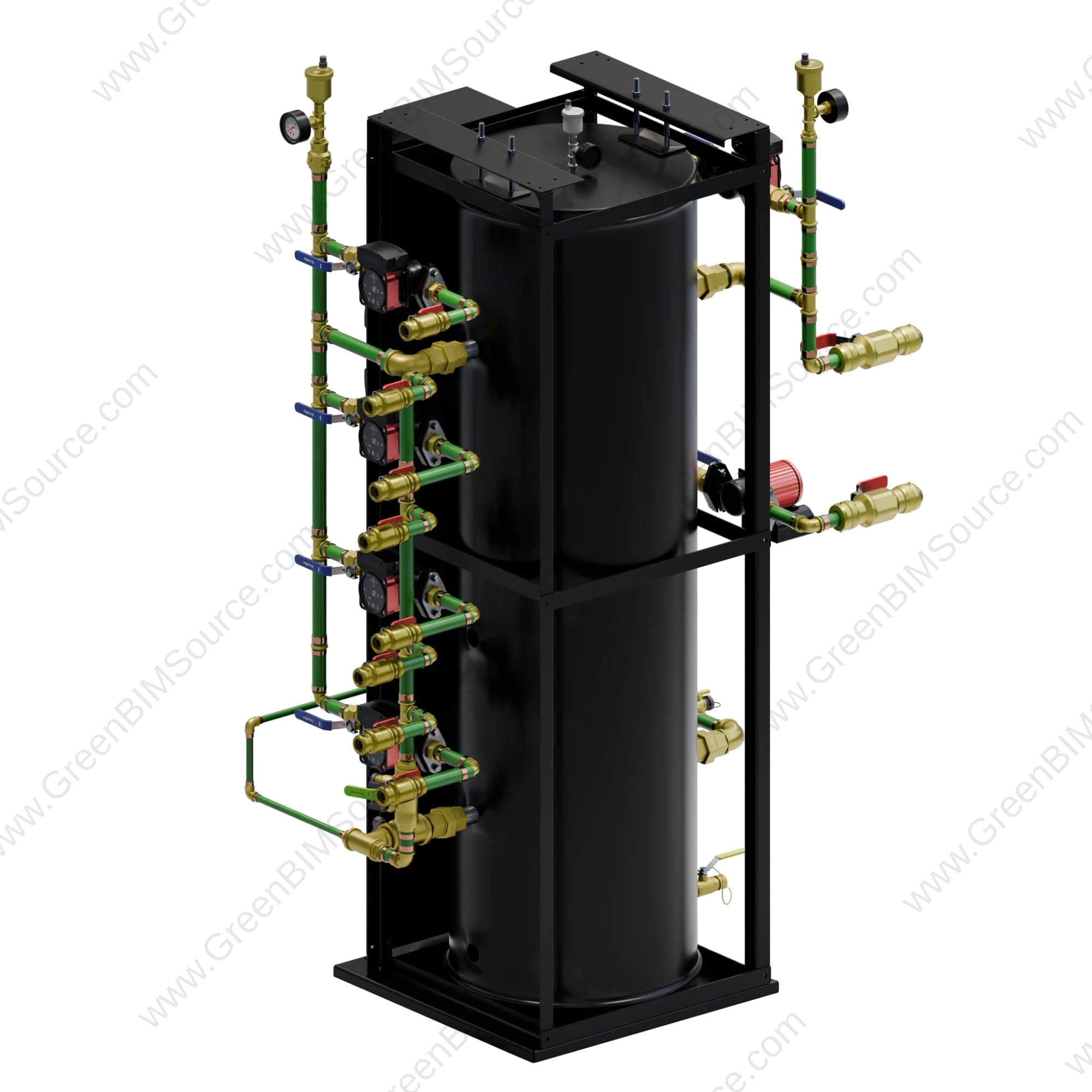
SolidWorks 3D CAD modeling and mechanical design of a packaged heat pump and hydronic system skid, brought to life with photorealistic Blender renders and an interactive 360° walkaround video.
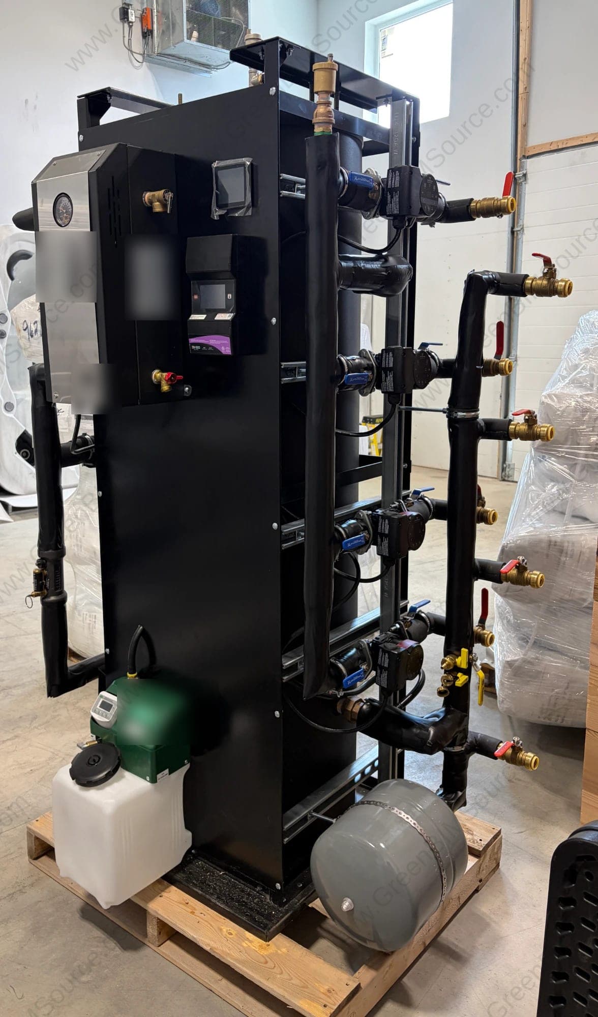
Challenge
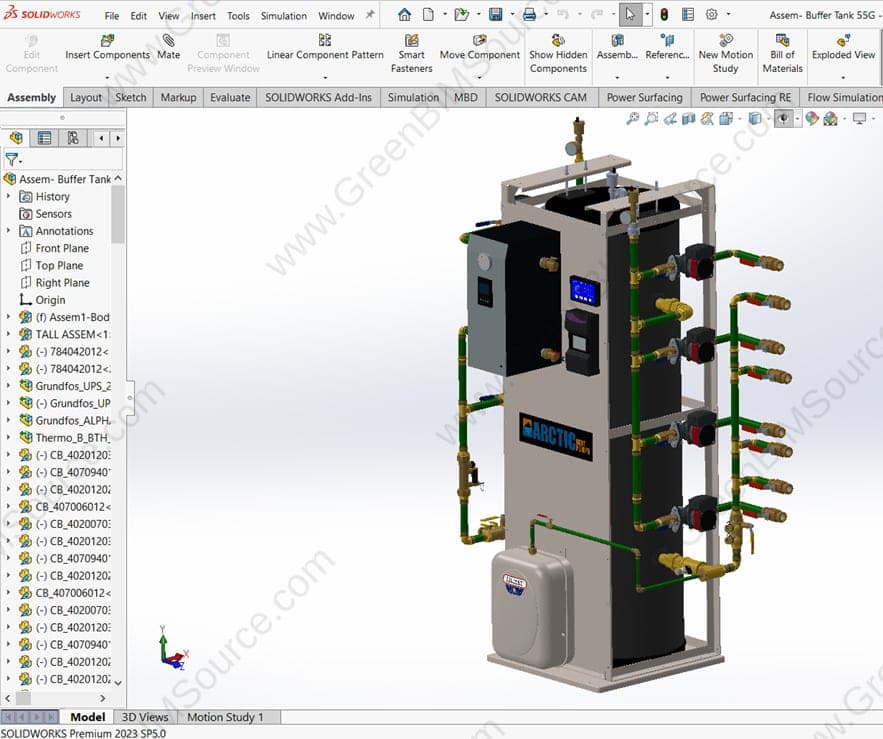
The project called for a compact, pre-assembled mechanical skid integrating a heat pump/hydronic unit, circulation pumps, isolation valves, an expansion tank, and a chemical feed system — all within a single transportable frame, with every component coordinated in 3D to avoid clashes and rework once fabrication began.
Approach
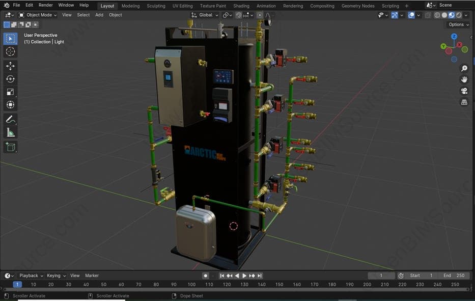
GreenBIMSource modeled every component of the skid individually in SolidWorks — the structural frame, hydronic unit, pump and valve manifolds, expansion tank, and chemical feed system — then assembled them into one coordinated 3D model to validate piping routing, component clearances, and service accessibility ahead of fabrication. The finished assembly was carried into Blender for photorealistic rendering and a 360° walkaround video, giving the client a fully interactive view of the skid before it left the shop floor.
Result
The 3D model matches the completed mechanical assembly shown below, confirming accurate piping routing, clearances, and component placement ahead of fabrication.
Deliverables
- SolidWorks 3D CAD assembly — frame, piping, and equipment
- Coordinated piping and valve manifold layout
- Component clearance and service-accessibility validation
- Photorealistic Blender renders and a 360° product walkaround video
- Assembly and fabrication-ready drawings
Have a Thermal Systems & Product Development project to discuss?
Send us your drawings, model, or project brief and we'll get back to you with scope and turnaround.