
Shell-and-Tube Heat Exchanger Thermal & Flow Analysis
A CFD-based thermal and flow analysis of a shell-and-tube exhaust-gas/water heat exchanger — quantifying pressure drop and heat-transfer performance from ANSYS Fluent simulation results and checking them against the design target.
Challenge
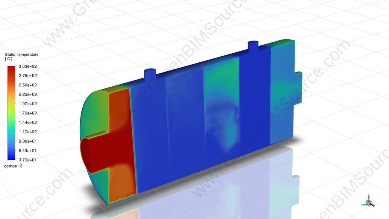
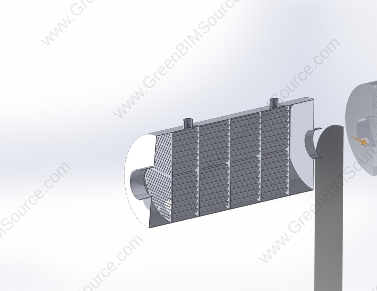
A shell-and-tube heat exchanger — 612 tubes carrying 300°C exhaust gas, water on the shell side at 60°C, three segmental baffles driving shell-side crossflow — needed its thermal performance and exhaust-side pressure drop quantified against a roughly 300 Pa design target before the design could be finalized.
Approach
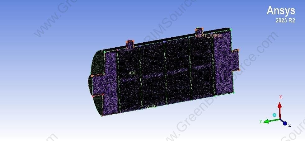
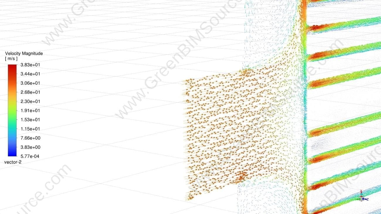
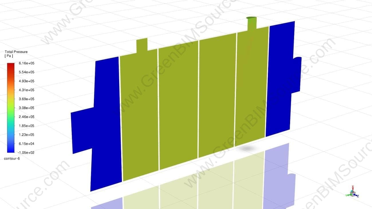
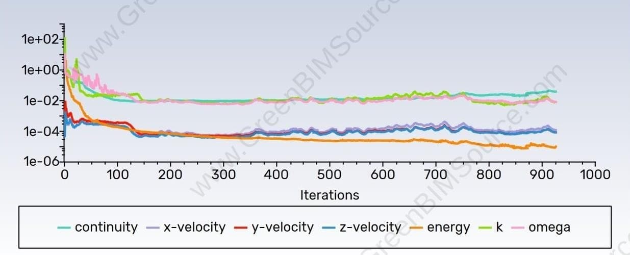
GreenBIMSource analyzed the exchanger's ANSYS Fluent CFD results — a symmetric half-domain model with 612 tubes (18.8/25.4 mm ID/OD, 1.5 m long), a 1.0 m shell, k–ω SST turbulence, and an ICEM CFD mesh of roughly 78.9 million elements — working through the temperature, velocity, and pressure fields, checking the solution's convergence against its residual history, and calculating the exhaust-side pressure drop and overall heat-transfer rate from the Fluent output.
Result
The analysis found a 575 Pa pressure drop across the tubes — notably above the roughly 300 Pa design target — and a heat-transfer rate of approximately 135 kW for the modeled half-domain, around 270 kW for the full exchanger. Based on the non-uniform gas-outlet temperature field, GreenBIMSource also recommended a mass-weighted outlet temperature calculation and a mesh-independence and energy-balance check to fully validate these figures before they're locked into the design.
Deliverables
- CFD thermal & flow performance analysis — ANSYS Fluent
- Pressure-drop and heat-transfer-rate calculations
- Convergence and residual-history review
- Engineering recommendations for further validation

Have a Thermal Systems & Product Development project to discuss?
Send us your drawings, model, or project brief and we'll get back to you with scope and turnaround.