
Mechanical BIM Modeling — Central Plant Equipment & Pipework
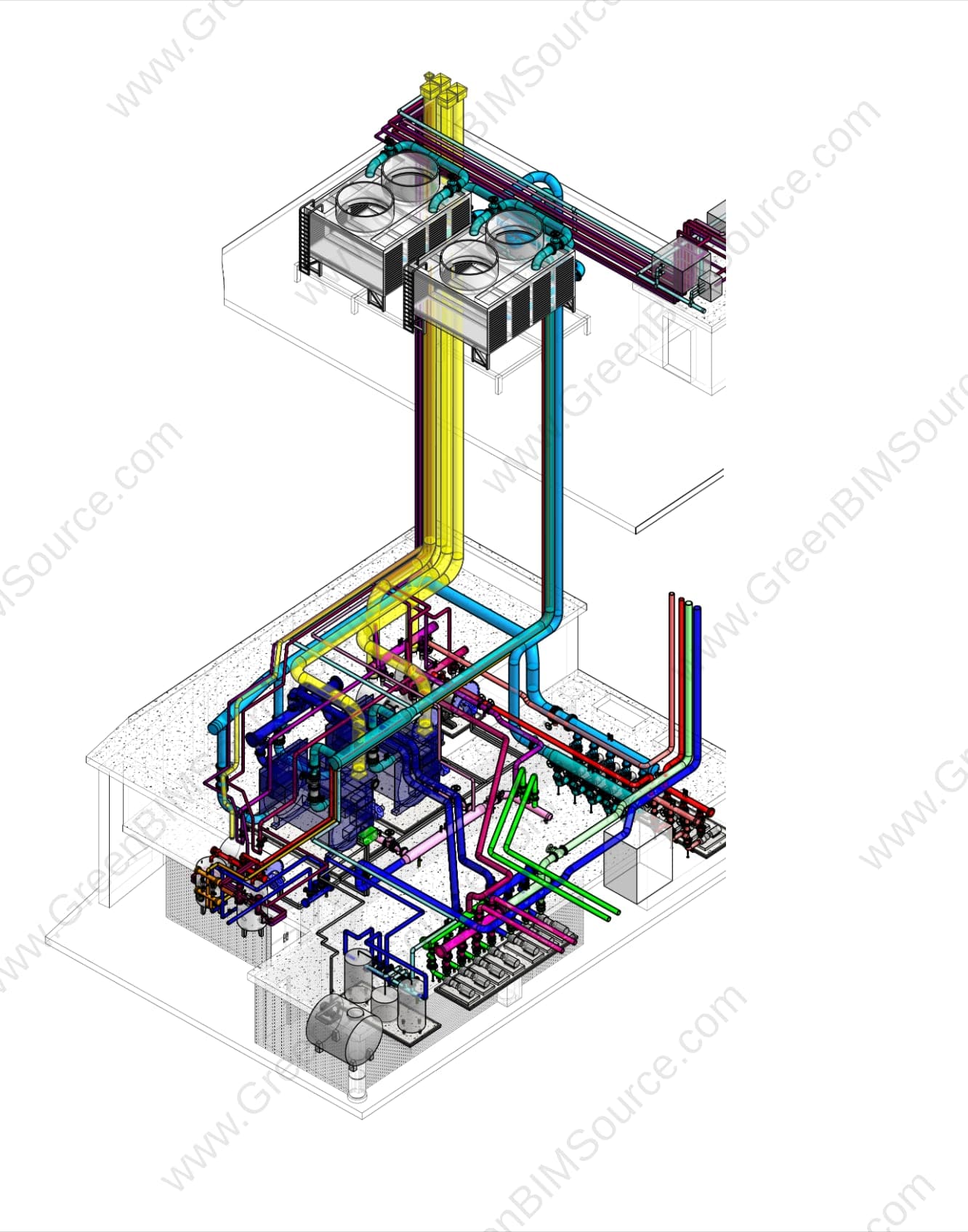
A Revit mechanical model of a central plant room — chillers, cooling towers, pumps, and pipework — modeled and sectioned in detail to support equipment coordination and construction.
Challenge
The central plant room packs chillers, cooling towers, pumps, and dense interconnecting pipework into a tight footprint, and needed a model precise enough to confirm clearances and generate reliable section details.
Approach
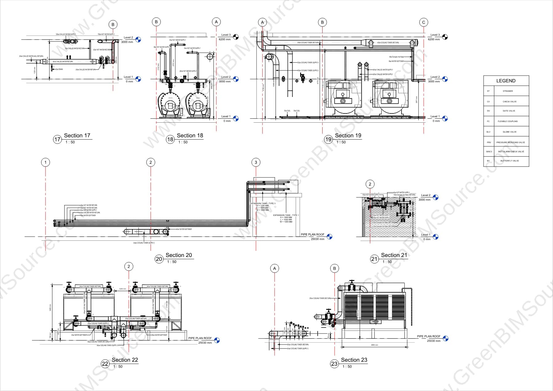
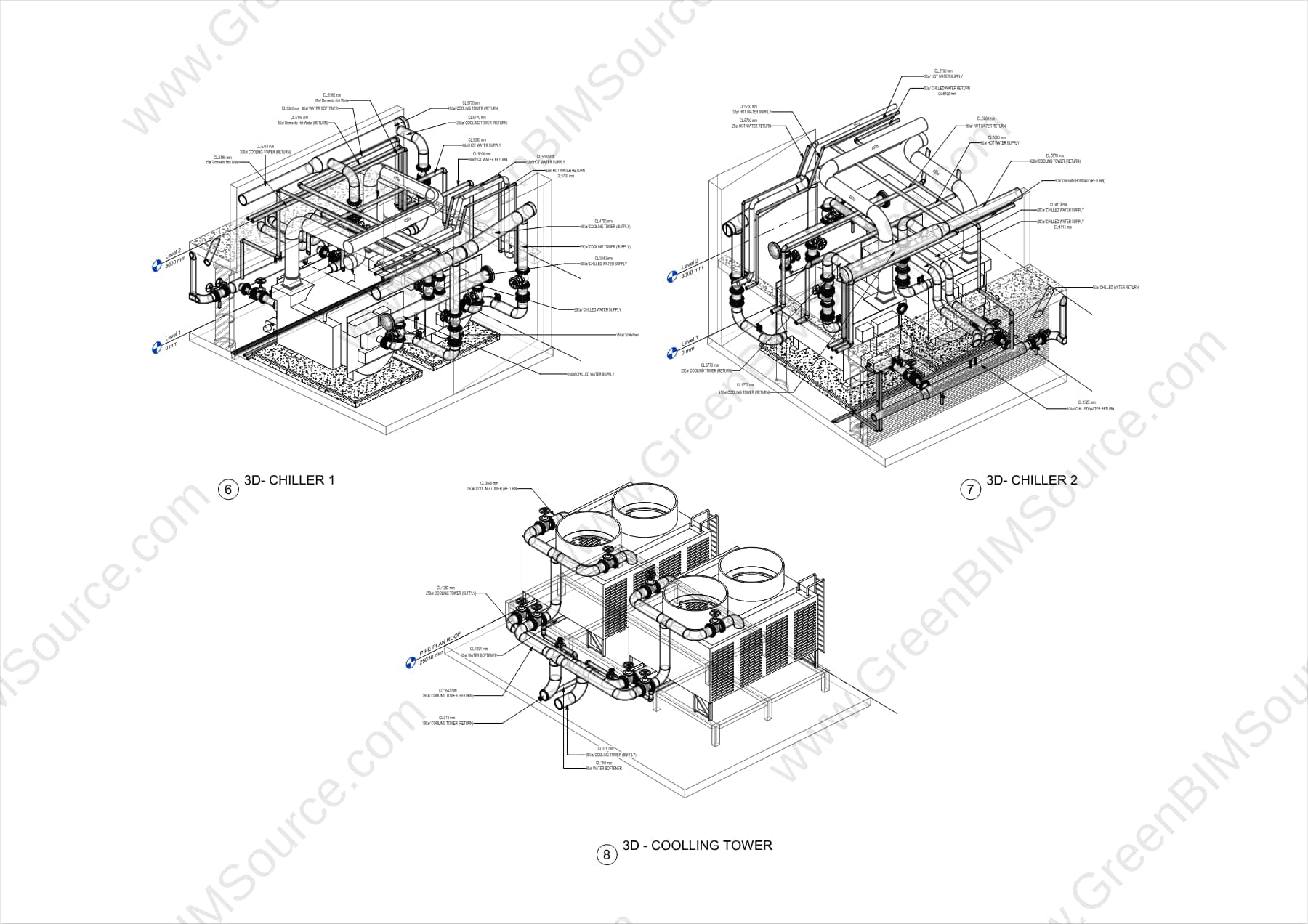
GreenBIMSource modeled the plant room's mechanical equipment and pipework in Revit and produced a full set of section cuts through the equipment — cooling towers, chillers, expansion tanks, and pump connections — to document routing and clearances.
Result
The sections below show the plant room's equipment and pipework modeled in detail — the kind of clash-checked, section-verified documentation a tightly packed mechanical room needs before construction.
Deliverables
- Revit mechanical model — plant room equipment and pipework
- Equipment section cuts (cooling towers, chillers, pumps, tanks)
- Coordination sheet set for construction documentation
Want the full sheet set? Download a watermarked sample of this deliverable.
Download Full Deliverable Sample (PDF)Have a BIM & MEP project to discuss?
Send us your drawings, model, or project brief and we'll get back to you with scope and turnaround.